Setup Guide for GuardPoint10 and Sensor Access Controllers
This guide explains how to connect and configure the Special Sensor Access QR Code Reader – OSDP Version with GuardPoint10 and supported Sensor Access controllers.
This setup has been tested using the reader in OSDP Plain mode.
At present, this guide should be followed for Plain / Open OSDP communication only. Secure OSDP modes may require additional configuration and are not covered in this article.
OSDP, or Open Supervised Device Protocol, is a modern access control reader communication protocol designed for RS485 reader communication. It supports bidirectional communication, reader supervision, and encrypted modes where supported. 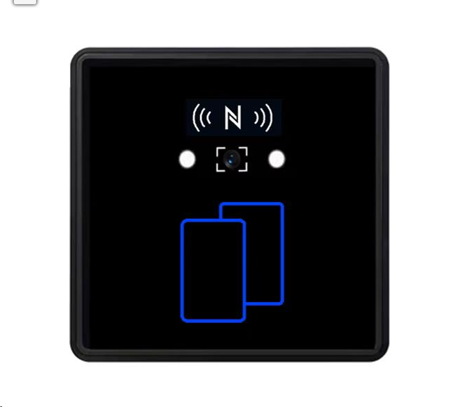
I. Prerequisites
Before installing the QR reader, make sure the following requirements are met.
1. Compatible Sensor Access Controller
The controller must support OSDP reader communication via the second RS485 communication port.
On IC2001 / IC4001 style controllers, this is the J10 / COM2 / H2-L2 connection area, not the standard reader ports.
2. KitCom2 Chips Installed
The controller must have the KitCom2 [U24 & U25 chips] installed.
These are the two communication ICs fitted near the second serial port, typically marked around U24 and U25 on the controller PCB.
If these chips are not fitted, the controller will not be able to communicate with OSDP readers on the second RS485 port. Please contact Sensor Access Support for further information or availability.
3. OSDP Firmware Installed on the Controller
The controller must be flashed with the correct OSDP firmware.
Tested firmware: TPLE32 OSDP 230222-AE CS=484F.HEX
This firmware should be attached at the bottom of this article for download.
For instructions on how to flash FW please refer to this link:
4. Reader Baud Rate
The OSDP reader must be configured to:
38400 baud
The OSDP integration notes also state that OSDP readers must be configured at 38400 baud, with each reader using a unique address.
5. Unique Reader Address
Each OSDP reader on the same RS485 bus must have a unique address.
Supported reader addresses:
01 to 04
Up to 4 OSDP readers can be connected to the controller’s second RS485 port in a daisy-chain arrangement.
II. Wiring the QR Reader
The QR reader is wired to the controller’s OSDP / RS485 COM2 connection, not to the normal reader inputs.
Use the controller terminals:
H2 / L2
These are normally found on the controller’s second RS485 port.
Reader Wire Colours
| QR Reader Wire | Function | Controller Connection |
|---|---|---|
| Red | +12V DC | 12V power supply |
| Black | GND / 0V | 0V / GND |
| Green | RS485-A | H2 |
| White | RS485-B | L2 |
Green = 485-A = RX = H2
White = 485-B = TX = L2
Red   = +12V
Black = GND / 0V
Important Wiring Notes
Do not wire the OSDP QR reader into the standard reader ports.
It must be wired into the special OSDP / COM2 RS485 block:
H2 / L2
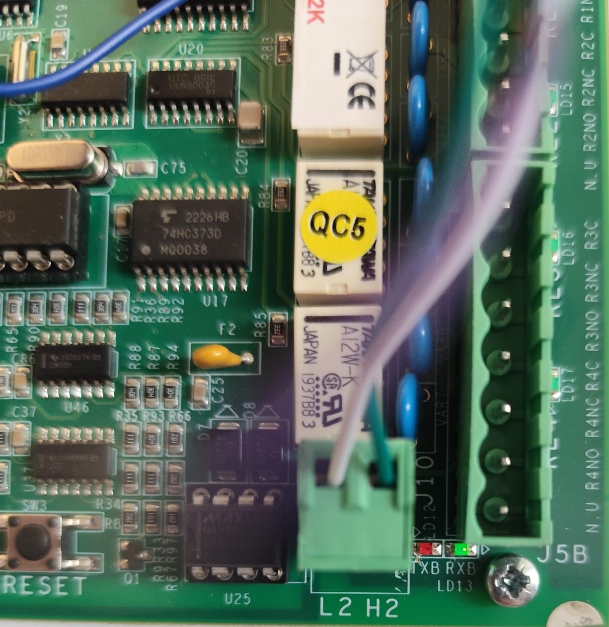
The reader connection works as a polling RS485 bus. This means multiple readers can share the same RS485 line, provided each reader has a different address.
Example layout:
Controller COM2 / OSDP Port
        H2  ------------------- Green / 485-A  Reader 1
        L2  ------------------- White / 485-B  Reader 1
        12V ------------------- Red            Reader 1
        0V  ------------------- Black          Reader 1

                         |
                         | Daisy-chain RS485
                         |

        H2  ------------------- Green / 485-A  Reader 2
        L2  ------------------- White / 485-B  Reader 2
        12V ------------------- Red            Reader 2
        0V  ------------------- Black          Reader 2
Up to 4 readers can be connected in this way, as long as each reader has its own OSDP address.
Recommended RS485 cable is twisted pair, typically 24 AWG. The OSDP notes specify AWG 24 with a maximum length of 1000 m, and advise a 120 Ω termination resistor at the RS485 termination ends for cable lengths greater than 61 m or where there is EMF interference.
III. Configuring the QR Reader
The QR reader is configured by scanning a special configuration QR code.
This QR code sets:
Baud rate
Reader address / RS485 ID
The configuration command format is
SKCFG{"mac":"6670CEBA","group":5001,"baudrate":38400,"rs485Id":1}
Only the following values should be changed:
baudrate
rs485Id
For this setup, the baud rate should be:
38400
The rs485Id should match the reader number required on the OSDP bus.
Any QR code generator can be used, as long as the QR code content type is set to plain text. Paste the full configuration command into the QR generator, create the QR code, then scan it using the QR reader. After the reader has scanned the setup QR code, restart the reader so the new settings are applied.
Generate a QR code using the full configuration command as plain text. Present the generated QR code to the reader so it can scan the configuration. Once the reader has accepted the QR code, restart the reader for the new baud rate and RS485 ID settings to take effect.
Creating the Configuration QR Code
Any QR code generation website can be used, provided the QR code type is set to: 'Text'
Paste the full configuration command into the QR generator, create the QR code, then present it to the reader.
After scanning the configuration QR code, restart the reader.
IV. Setting up the Reader in GuardPoint10
Once the reader is wired and configured, it must be set correctly in GuardPoint10.
Go to:
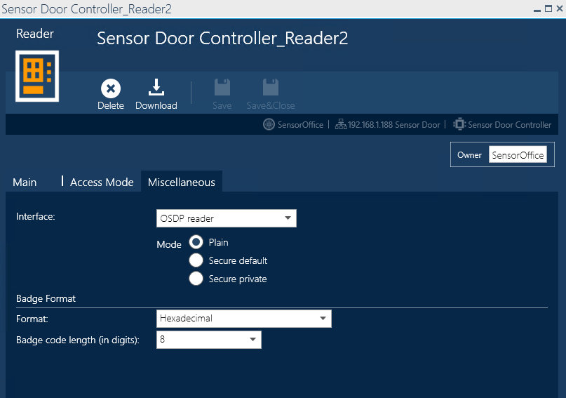
Setup > Infrastructure > Controller > Reader > Miscellaneous
Then change:
Interface = OSDP reader
For the tested setup, set:
Mode = Plain
Then configure the badge format as required for the site.
For example, in the tested screenshot:
Format: Hexadecimal
Badge code length: 8
The GuardPoint10 manual notes that when OSDP reader is selected, the available modes are Plain, Secure Default, and Secure Private, and that OSDP requires connection to COM2 with KitCom2 and the correct firmware.
V. Summary
The OSDP version of the Sensor Access QR reader must be connected to the controller’s dedicated H2 / L2 RS485 OSDP port, not the standard reader inputs. Before testing, make sure the controller has the KitCom2 chips installed, the correct OSDP firmware loaded, and the QR reader has been configured by QR code for 38400 baud with a unique RS485 ID. In GuardPoint10, set the reader interface to OSDP reader and use Plain mode for this tested setup.
Was this article helpful?
That’s Great!
Thank you for your feedback
Sorry! We couldn't be helpful
Thank you for your feedback
Feedback sent
We appreciate your effort and will try to fix the article